


Posted 1425 days ago
There are multiple workflows to restore bridges supported by implants with CEREC. The workflow of software and tibase of Cerec is a good option to restore crowns of individual implants, but this workflow is much more work to restore bridges. This is the typical Carec Tibase workflow for implant bridges:
- Scan the retention implants with a Syrona Dentsply Scanpost
- Design individual divided restorations for each implant
- Mill only stirrups
- Link each pillar to a tibase
- Bring the patient to insert the pillars and scan in the mouth
- Try the pillars as teeth and design a conventional bridge
Atlantis’s workflow allows retention implants to scan in a similar way, but using an atlantis IO Flo Scanbody. The scans are sent through the Connect software to the Dentspy Sarcona implants. According to the recipe, the clinician can request that the stirrups be parallel to have a passive adjustment bridge. Then a central file is returned to design and manufacture the bridge. This workflow implies less quotes and results in an excellent adjustment bridge. These are the steps in the typical atlantis workflow for implant bridges:
- Scan the retention implants with a flour and send to Atlantis (implants of Syrona)
- Request parallel pillars and approve the design
- Open the central archive, design and manufacture of a conventional bridge
- Stirrups and bridge
This case involved a failed bridge of #18-21 (images 1 and 2). Both #18 and #21 were not restorable. The patient had a CBCT Axeos exploration and an optical scan with CEREC chair software 5.1.2. The #19, 20 and 21 teeth were virtual extracted from the model (image 3), and the implants were planned in the Sicat 2.0 software in positions #19 and #21 (image 4). The restorative plan was to manufacture a bridge of three units from #19 to #21. Two CEREC guides 3 surgical guides were manufactured to Ensure proper implant placement (image 5). The bridge was sectioned, leaving #18 instead to help support surgical guides (image 6). The tooth #21 was extracted, and the implants were placed on sites #19 and #21 (image 7 and 8). Then the tooth #18 was extracted. IO FL SCANBODIES were placed and images were made to manufacture custom healing pillars for implants #19 and #21 (image 9). The stock healing pillars were reduced to the implants, and sutures were placed (image 10). The Flo Scan was a prayer to the implants of Sirina Dentspplery. Personalized healing stages arrived two days later. When the patient returned for the one -week post, the healing states of the healing states were replaced by the personalized healing pillars.
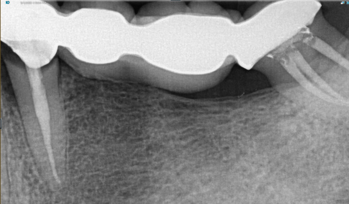
Image 1. preassemble radiography o Failure bridge #18-21

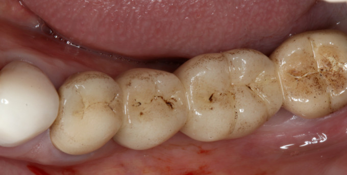
Image 2. Previous bridge
![]()
Image 3. OhPRE-OP PICAL SHIPS Virtual and Bridge Extraning #19-21

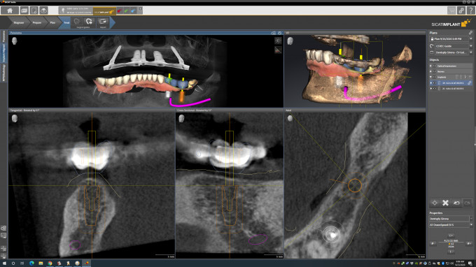
Image 4. I.Moving planning in Sicat 2.0 Implant module
![]()
Image 5. dSurgical guide of Esigna and Ground

Image 6. bSectioned and eliminated crest
![]()
Image 7. cG3 Surgical guide for position #19
![]()
Image 8. G.outside Ostetomy For implant #19

Image 9. I.O Floing at the time of surgery for personalized healing flats
![]()
Image 10. cOmpleted surgery with stock healing pillars
![]()
Image 11. aTlantis designed custom cure pillars
The advantage of personalized healing floors is to develop the duration of the perfectly contoured tissue the initial healing process. After the implants are integrated, there is an option to alter the design of the healing pillar to create the final pillars using the same contours. This eliminates the need for images after healing. In this case, however, the decision was made for the patient to return for new images. In the week after surgery, the implants were photographed with flos for the final stadiums. The file was the prayer to the implants of Sirina Dentspplery through the Connect 5.1 software. A recipe on Atlantis Weborder was completed requesting parallel titanium pillars with concave emergency and tissue support for implants #19 and #21 (image 12). An insertion guide was also requested to ensure that the pillars were placed in the right position.
![]()
Image 12. Atlantis designed final stadiums
A few hours later, the central archive was ready. The model, with the stirrups placed in Virtualy #19 and #21, imported to the Cerec Chairide 5.1 software (image 13). A zirconia bridge of three units was designed and manufactured (Image 14). In the delivery, the personalized healing pillars were eliminated, the final pillars became in position with the help of the insertion guide and the zirconium bridge was cemented with RMGI cement (images 15-18). There was no need for anesthesia and almost without whitening the tissue. Due to the precise digital images of the gingiva with a primescan, the contours of the final pillar were a perfect combination of the contours of the personalized healing pillar.

Image 13. doPillars Mineral Archives placed in Virtualy
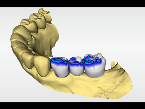
Image 14. Designed bridge #19-21 from the Central Archive

Image 15. I.NSertion Guide with pillars and milling bridge
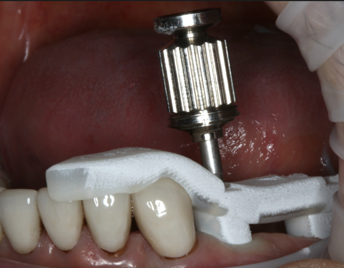
Image 16. aButments sitting and exhausted with the insertion guide
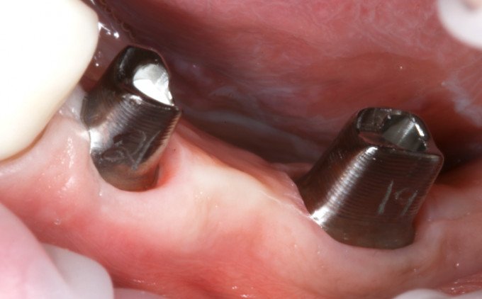
Image 17. fInal titanium piros #19 and #21

Image 18. fInal cemented bridge #19- #21
Atlantis’s workflow produced perfectly contoured and parallel titanium pillars, without having to manufacture the president of the pillars or join them to a tibase. As an additional advantage, the central archive that was included with the stirrups allowed the final bridge to be designed and manufactured without having to place or scan the pillars intrarally. Atlantis’s workflow not only produces a precise adjustment implant bridge, but also saves valuable time for both the dentist and the patient.


